Current Trends in Microwave Backhaul

Microwave Backhaul: Current and Future Trends

What’s happening in Microwave Backhaul? According to the Ericsson Mobility Report Q4 2017, 3.3 billion mobile broadband subscribers will be added  in the next five years, and a clear majority of these will come from LTE and 3G/HSPA in microwave-centric markets. The addition of an Indian greenfield LTE/4G operator and the densification needed to support proper MBB services will increase the number of sites, stabilizing microwave share on a global basis.
The large-scale 5G volume deployments are initially expected in areas with high fiber penetration, such as China, Korea, Japan and US.
There are also operators in Western Europe that have a combination of microwave and fiber, and are looking at introducing 5G. Larger volume rollouts of 5G networks are planned for a later point in the next few years.

CableFree-Microwave-Fiber-Copper-Backhaul-Global-to-2022

Backhaul media distribution (excluding China, Japan, Korea and Taiwan)


CableFree-Microwave-Fiber-Copper-Backhaul-Regions

In mature mobile broadband regions such as Western Europe, there are
examples of large operators using up to 80 percent microwave that now
plan for 5G introduction using existing microwave networks. Microwave
technology has evolved to manage the demand of mobile networks,
and can do so from any macro site. Core and inter-city aggregation
networks are typically deployed with fiber backhaul, while spurs are
implemented using microwave. It has also been observed that usage of
lower spectrum for longer-distance hops is decreasing in favor of
higher-frequency bands for short distance and high-capacity hops.
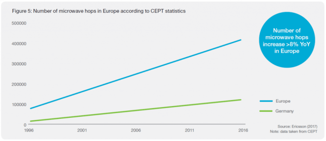
Number of Microwave Hops in Europe according to CEPT

Spectrum trends up to 2025

Spectrum below 3GHz will provide coverage in 5G. The 3–5GHz spectrum will enable high bandwidth balanced with good coverage. These bands are not used by microwave today to any major extent (apart from some 4 and 5GHz long-haul links). The extreme bandwidths in 5G will be enabled for hotspots and industry applications in spectrum above 20GHz.
It is clear that the main focus will be on bands 24–42GHz. In the US the FCC currently has a 24, 28 and 38GHz focus and in Europe there is a focus on 26GHz. 3GPP is specifying 5G bands in 24.25–29.5GHz and 37–43.5GHz in Release 15. It excludes 32GHz and E-band, which are both part of the ITU study and, in a recent report, the FCC stresses the importance of E-band for 5G backhaul. The decision on which bands to use and where, will be unique to each nation. But longterm parts of the 24–42GHz spectrum will be used more by 5G and less by microwave fixed services. In some of these bands, e.g. 26 and 38GHz
in Europe, there are many existing microwave links in several countries.
It will take time to move these links to other bands such as E-band. The 15–23GHz spectrum will remain as the global high-volume microwave bands. E-band will become a global high-volume band, both on its own and in a multi-band booster combination with 15–23GHz.
For long hops and as an economical replacement to fiber, 6–13GHz will also remain important. Due to their good propagation properties in geographical areas with high rain rates, these low frequencies are fundamental to building transport networks in certain regions.
With all of this taken into account, it is clear that the availability and usage of microwave spectrum will go through a major transformation in the next 5 to 10 years

CableFree Microwave New deployment share per frequency range
New deployment share per frequency range

Higher Capacities: Radio Link Aggregation

When combining data over multiple carriers, radio link bonding is a key technology. An efficient bonding technique ensures that a single data stream is seamlessly transmitted across different radio channels, with negligible overhead.  In the current Global market: About 80 percent of links are configured as single carriers (1+0), the remainder as multi-carrier links with backup links as protection. About 8 percent are set up with one active radio and the protection link in hot standby mode (1+1); 10 percent are configured with dual-carrier radio link bonding (2+0), where the capacity of the backup link is used to increase the link’s peak capacity. Only 2 percent are configured for three or more carriers (>2+0). Due to the need for increased transport capacity, the number of links aggregated over two or more carriers is rising globally.

CableFree Microwave Global distribution of radio link configurations. 80 percent are configured as single-carrier links (1+0), 20 percent are configured as multiple radio links
Global distribution of radio link configurations. 80 percent are configured as single-carrier links (1+0), 20 percent are configured as multiple radio links

Total Cost of Ownership (TCO) and Return-on-Investment (ROI)

The total cost of ownership and time-to-market becomes critical to
secure the overall operator business case. As fiber investments typically
have a depreciation of around 25 years, and 5–8 years for microwave,
it becomes important to invest in fiber within the right areas, such
as core and aggregation networks, which historically have been
deployed with long-haul microwave.

Technology Evolution for Microwave

Over the past 20 years, microwave technology has been continuously
evolving to meet requirements. In 1996, microwave hops typically
supported 34Mbps, whereas today products have the ability to support
up to 1Gbps in traditional bands, and up to 10Gbps with E-Band.

Microwave Technology Roadmap and Evolution

Acknowledgement

Some content is (C) Ericsson reproduced with thanks, from Ericsson Mobility Report Q4 2017

For Further Information

For More Information on Microwave Links, Please Contact Us


Microwave Antenna Alignment

Alignment of Microwave Antennas for Digital Microwave Transmission Systems

This article contains generic instructions for alignment of Microwave antennas.  Specific products may have different features, in which case please refer to the documentation provided for those products:

CableFree Microwave Antenna Alignment

Antenna Alignment for Microwave Links

This guide explains how to achieve the optimal antenna alignment of microwave antennas when used with modern digital microwave products.  Before attempting to do the alignment it is highly recommended that you read this guide in detail.  For specific commands please consult the manual of the product being installed

Step 1:  Preparation:

Mount the antenna on the tower according to the antenna installation instructions:  Ensure that the adjustment bolts move smoothly and the range of motion is sufficient for the expected angle of up and down (elevation) tilt. Ensure that the mount itself is attached securely and all safety precautions have been taken.

CableFree Microwave Antenna Alignment using DVM

Step 2: Coarse Alignment:

Visually align the antenna with the far end.  The most common ways to do this are :

1)      If the visibility is good and the sun is in the correct position, have someone at the far end location reflect the sun with a mirror so the location is obvious.

2)      If visibility is poor, use GPS coordinates and a GPS compass to aim the antenna coarsely.

CableFree Microwave Antenna Alignment avoiding Sidelobes

Step 3: Fine Alignment.

Before conducting fine alignment, the ODUs at both ends of the link must be attached properly to the antenna via the direct mount or remote mount (using Waveguide) and the far end ODU must be powered on and transmitting.  The ODU lightning surge suppressors and grounding provisions should be put in place as well before alignment. The local ODU must be powered on, but need not be transmitting.

Ensure that:

1)      Frequency of the far end transmitter matches the frequency of the local receiver.

2)      The TX output power is not set above the level of the license.

3)      ATPC is turned OFF on the far end.

4)      Alignment mode is ON for SP ODUs – Display on ODU and IDU will update at 5 times per second.

FINE ALIGNMENT PROCEDURE

1)      Adjust the azimuth over a 30 degree sweep by turning the adjustment bolt in increments of 1/10th turn to avoid missing the main lobe. When the highest signal has been found for azimuth, repeat for the elevation adjustment.

2)      Turn the local transmitter on to allow alignment at the far end.

3)      Move to the far end of the link and repeat step 1.

4)      Lock down the antenna so no further movement can occur.

5)      Install the antenna side struts supplied with the antenna.

6)      Verify the RSSI remains the same and is within 2-4 dB of the expected levels.

7)      Check the ODU connector seals.

8)      Turn alignment mode OFF

9)      The alignment is complete.

FDD and TDD Explained

The difference between FDD and TDD in Microwave Transmission

Microwave ODU with Antenna using FDD (Frequency Division Duplex)

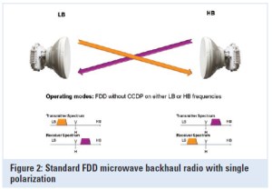
Microwave links typically use Frequency-division duplexing (FDD) which is a method for establishing a full-duplex communications link that uses two different radio frequencies for transmitter and receiver operation. The transmit direction and receive direction frequencies are separated by a defined frequency offset.

Advantages of FDD

In the microwave realm, the primary advantages of this approach are:

  • The full data capacity is always available in each direction because the send and receive functions are separated;
  • It offers very low latency since transmit and receive functions operate simultaneously and continuously;
  • It can be used in licensed and license-exempt bands;
  • Most licensed bands worldwide are based on FDD; and
  • Due to regulatory restrictions, FDD radios used in licensed bands are coordinated and protected from interference, though not immune to it.
Microwave FDD (Frequency Division Duplexing)

Disadvantages to FDD

The primary disadvantages of the FDD approach to microwave communication are:

  • Complex to install. Any given path requires the availability of a pair of frequencies; if either frequency in the pair is unavailable, then it may not be possible to deploy the system in that band;
  • Radios require pre-configured channel pairs, making sparing complex;
  • Any traffic allocation other than a 50:50 split between transmit and receive yields inefficient use of one of the two paired frequencies, lowering spectral efficiency; and
  • Collocation of multiple radios is difficult.

TDD compared with FDD

Time-division duplexing (TDD) is a method for emulating full-duplex communication over a half-duplex communication link. The transmitter and receiver both use the same frequency but transmit and receive traffic is switched in time. The primary advantages of this approach as it applies to microwave communication are:

  • It is more spectrum friendly, allowing the use of only a single frequency for operation and dramatically increasing spectrum utilization, especially in license-exempt or narrow-bandwidth frequency bands ;
  • It allows for the variable allocation of throughput between the transmit and receive directions, making it well suited to applications with asymmetric traffic requirements, such as video surveillance, broadcast and Internet browsing;
  • Radios can be tuned for operation anywhere in a band and can be used at either end of the link. As a consequence, only a single spare is required to serve both ends of a link.

Disadvantages of TDD

The primary disadvantages of traditional TDD approaches to microwave communications are:

  • The switch from transmit to receive incurs a delay that causes traditional TDD systems to have greater inherent latency than FDD systems;
  • Traditional TDD approaches yield poor TDM performance due to latency;
  • For symmetric traffic (50:50), TDD is less spectrally efficient than FDD, due to the switching time between transmit and receive; and
  • Multiple co-located radios may interfere with one another unless they are synchronized.


Microwave Mobile Backhaul

Packet Microwave Radios for Mobile Backhaul

To deliver a compelling quality of experience for subscribers, you must respond quickly to growing traffic demands. Modern Packet Microwave Mobile Backhaul products help you maximize the network’s performance by enabling rapid deployment of scalable backhaul to cell sites.  Modern solutions include a portfolio of microwave products to address the backhaul needs of 2G, 3G, and LTE macro cells and 3G, LTE, and Wi-Fi® small cells. Radio spectrum is maximized using innovative techniques to maximize payload capacity to support the evolution to LTE and heterogeneous networks. Unique, common radio support for indoor and outdoor deployments enhances savings potential.

Packet Microwave Mobile Backhaul is a key component in a modern end-to-end mobile backhaul solution, which provides the flexibility, scale and operational simplicity to lower the total cost of ownership and simultaneously enhance the mobile service experience.

BENEFITS

CableFree Microwave for Mobile Backhaul

Economic benefits

Rapidly support the optimal cell site location

  • Complete backhaul portfolio for macro cells and small cells
  • Support for all sites including both end and intermediate cell sites
  • Space and power efficiency
  • Full outdoor option to meet different microwave site space requirements

Achieve maximum spectral performance

  • Maximum bandwidth per band
  • Intelligent compression
  • Advanced quality of service levels supporting subscriber quality of experience

Scale the network cost effectively

  • Reliably bond radio channels to create larger microwave links
  • Any topology, any number of microwave link directions
  • Network awareness for both Carrier Ethernet and/or IP/MPLS networks

Be operationally efficient

  • Common radio for all cell sites
  • Evolutionary path from hybrid microwave to packet microwave at the touch of a button
  • Management beyond basic IP partner integration

Deployment, management, end-user benefits

Grow and retain subscribers by maximizing the mobile experience

  • Infrastructure support for increased subscriber bandwidth demands
  • Ability to react quickly to subscriber demand with optimally-located cell sites
  • Increased capacity that supports high bandwidth data applications

COMPONENTS

4G/LTE Mobile Backhaul

Packet Microwave Mobile Backhaul integrates a modern microwave portfolio with small cell optimized products to provide a complete backhaul offering for small cells and/or macro cells.

Read on in our following pages to find out more about technologies used in mobile backhaul applications

Welcome to Microwave-Link.com

Welcome to Microwave-Link.com

Find out information on technology, deployment and applications for modern Digital Microwave Links

Microwave Link
CableFree MW Link installed on a telecom tower

Microwave links are widely used for connectivity in modern digital IP networks. With capacities up to 6Gbps and beyond, a modern Microwave Link network can deliver bandwidth in a reliable, cost-effective and flexible manner – without need for disruption and delay caused by digging up streets and avoiding costly leased-line or leased fibre optic alternatives.

On this website you can find more information about radio link deployment and technology.  Also we invite you to contact our experts with any questions by sending a message to us on our contact page.

CableFree Microwave Links used for Mobile Backhaul
CableFree MW Radio Links used for Mobile Backhaul

Microwave links are used extensively in 4G & 5G LTE backhaul networks, 2G (GSM) and 3G (UMTS) mobile operators, wireless metropolitan area networks (Wi-MAN) and corporate networks where high performance, flexibility, speed of deployment and low operating costs are required.  Key features of links include high spectral efficiency (256QAM, 1024QAM, 2048QAM and 4096QAM), Automatic Transmit Power Control (ATPC) and Adaptive Coding and Modulation (ACM).

Globally, MW radio links are used for around 60% of all mobile backhaul connections due to the compelling technical and commercial arguments in favour of MW radio compared to leased line and trenched fibre alternatives.  Speed of deployment and flexibility – the ability to move sites or provision rapidly – are greatly in favour of MW radio over fibre and cabled alternatives.

A Full Outdoor Microwave Link installed for ISP in Iraq with 880Mbps Full Duplex Capacity

A  link typically features a radio unit and a parabolic antenna, which may vary in size from 30cm up to 4m diameter depending on required distance and capacity.  The radio unit is generally either a “Full Outdoor”, “Split Mount” or “Full Indoor” design depending on operator preference, deployment, features and available indoor space for specific sites and installation.

CableFree FOR3 Full Outdoor 1024QAM Microwave Link
Full Outdoor 1024QAM MW Radio Link

For More information on MW Radio Links please Contact Us