What’s happening in MicrowaveBackhaul? According to the Ericsson Mobility Report Q4 2017, 3.3 billion mobile broadband subscribers will be added in the next five years, and a clear majority of these will come from LTE and 3G/HSPA in microwave-centric markets. The addition of an Indian greenfield LTE/4G operator and the densification needed to support proper MBB services will increase the number of sites, stabilizing microwave share on a global basis.
The large-scale 5G volume deployments are initially expected in areas with high fiber penetration, such as China, Korea, Japan and US.
There are also operators in Western Europe that have a combination of microwave and fiber, and are looking at introducing 5G. Larger volume rollouts of 5G networks are planned for a later point in the next few years.
Backhaul media distribution (excluding China, Japan, Korea and Taiwan)
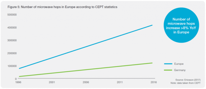
In mature mobile broadband regions such as Western Europe, there are
examples of large operators using up to 80 percent microwave that now
plan for 5G introduction using existing microwave networks. Microwave
technology has evolved to manage the demand of mobile networks,
and can do so from any macro site. Core and inter-city aggregation
networks are typically deployed with fiber backhaul, while spurs are
implemented using microwave. It has also been observed that usage of
lower spectrum for longer-distance hops is decreasing in favor of
higher-frequency bands for short distance and high-capacity hops.
Number of Microwave Hops in Europe according to CEPT
Spectrum trends up to 2025
Spectrum below 3GHz will provide coverage in 5G. The 3–5GHz spectrum will enable high bandwidth balanced with good coverage. These bands are not used by microwave today to any major extent (apart from some 4 and 5GHz long-haul links). The extreme bandwidths in 5G will be enabled for hotspots and industry applications in spectrum above 20GHz.
It is clear that the main focus will be on bands 24–42GHz. In the US the FCC currently has a 24, 28 and 38GHz focus and in Europe there is a focus on 26GHz. 3GPP is specifying 5G bands in 24.25–29.5GHz and 37–43.5GHz in Release 15. It excludes 32GHz and E-band, which are both part of the ITU study and, in a recent report, the FCC stresses the importance of E-band for 5G backhaul. The decision on which bands to use and where, will be unique to each nation. But longterm parts of the 24–42GHz spectrum will be used more by 5G and less by microwave fixed services. In some of these bands, e.g. 26 and 38GHz
in Europe, there are many existing microwave links in several countries.
It will take time to move these links to other bands such as E-band. The 15–23GHz spectrum will remain as the global high-volume microwave bands. E-band will become a global high-volume band, both on its own and in a multi-band booster combination with 15–23GHz.
For long hops and as an economical replacement to fiber, 6–13GHz will also remain important. Due to their good propagation properties in geographical areas with high rain rates, these low frequencies are fundamental to building transport networks in certain regions.
With all of this taken into account, it is clear that the availability and usage of microwave spectrum will go through a major transformation in the next 5 to 10 years
New deployment share per frequency range
Higher Capacities: Radio Link Aggregation
When combining data over multiple carriers, radio link bonding is a key technology. An efficient bonding technique ensures that a single data stream is seamlessly transmitted across different radio channels, with negligible overhead. In the current Global market: About 80 percent of links are configured as single carriers (1+0), the remainder as multi-carrier links with backup links as protection. About 8 percent are set up with one active radio and the protection link in hot standby mode (1+1); 10 percent are configured with dual-carrier radio link bonding (2+0), where the capacity of the backup link is used to increase the link’s peak capacity. Only 2 percent are configured for three or more carriers (>2+0). Due to the need for increased transport capacity, the number of links aggregated over two or more carriers is rising globally.
Global distribution of radio link configurations. 80 percent are configured as single-carrier links (1+0), 20 percent are configured as multiple radio links
Total Cost of Ownership (TCO) and Return-on-Investment (ROI)
The total cost of ownership and time-to-market becomes critical to
secure the overall operator business case. As fiber investments typically
have a depreciation of around 25 years, and 5–8 years for microwave,
it becomes important to invest in fiber within the right areas, such
as core and aggregation networks, which historically have been
deployed with long-haul microwave.
Technology Evolution for Microwave
Over the past 20 years, microwave technology has been continuously
evolving to meet requirements. In 1996, microwave hops typically
supported 34Mbps, whereas today products have the ability to support
up to 1Gbps in traditional bands, and up to 10Gbps with E-Band.
Microwave Technology Roadmap and Evolution
Acknowledgement
Some content is (C) Ericsson reproduced with thanks, from Ericsson Mobility Report Q4 2017
For Further Information
For More Information on Microwave Links, Please Contact Us
70GHz to 80GHz bands (E-band) are used for Point to Point (P2P) Microwave (Millimeter Wave, MMW) Radio Links
Sources of Data and Graphics
All contents (C) OFCOM and taken from:
OfW48 UK Frequency Allocations for Fixed (Point-to-Point) Wireless Services and Scanning Telemetry This document shows the current bands managed by Ofcom that are available for fixed terrestrial (point to point) links and scanning telemetry in the UK.
Technical regulations
The Radio Equipment and Telecommunications Terminal Equipment Directive
99/5/EC (R&TTED) has been implemented in ‘The Radio Equipment and Telecommunications Terminal Equipment Regulations 2000, Statutory
Instrument (SI) 730. In accordance with Articles 4.1 and 7.2 of the R&TTED
the:
• IR2000: The UK Interface Requirement 2000 contains the requirements for the licensing and use of fixed (point-to-point) wireless services in the UK.
• IR2037: The UK Interface Requirement 2037 applies for scanning telemetry services.
• IR2078: The UK Interface Requirement 2078 applies for the 60 GHz band
Notes specific to the frequency charts
The first column describes each available frequency band, represented by a diagram (not to scale). The frequency band limits are listed below the diagram; frequencies below 10 GHz are represented in MHz, while those above 10 GHz are in GHz. The width of each guard band is shown above the diagram, and is always specified in MHz.
The channel arrangements in some bands are staggered, so that the width and position of the guard band vary for different channel spacings. In these cases, a table underneath gives details of the guard bands for different spacings (with all frequencies in MHz).
The first column also includes the title of the relevant international recommendations for each band, produced by the European Conference of Postal and Telecommunications (CEPT) or the International Telecommunication Union (ITU). CEPT recommendations are available at https://www.cept.org/ecc/ and ITU Recommendations at https://www.itu.int.
The final column contains the channel spacing for duplex operation in each frequency band except for bands above 60 GHz. Details of standard systems assigned in the UK are shown in the relevant technical frequency assignment criteria.
For Further Information
For More Information on Microwave Planning, Please Contact Us
58GHz, 60GHz and 65GHz bands are used for Point to Point (P2P) Microwave Radio Links. Also called V-band
Sources of Data and Graphics
All contents (C) OFCOM and taken from:
OfW48 UK Frequency Allocations for Fixed (Point-to-Point) Wireless Services and Scanning Telemetry This document shows the current bands managed by Ofcom that are available for fixed terrestrial (point to point) links and scanning telemetry in the UK.
Technical regulations
The Radio Equipment and Telecommunications Terminal Equipment Directive
99/5/EC (R&TTED) has been implemented in ‘The Radio Equipment and Telecommunications Terminal Equipment Regulations 2000, Statutory
Instrument (SI) 730. In accordance with Articles 4.1 and 7.2 of the R&TTED
the:
• IR2000: The UK Interface Requirement 2000 contains the requirements for the licensing and use of fixed (point-to-point) wireless services in the UK.
• IR2037: The UK Interface Requirement 2037 applies for scanning telemetry services.
• IR2078: The UK Interface Requirement 2078 applies for the 60 GHz band
Notes specific to the frequency charts
The first column describes each available frequency band, represented by a diagram (not to scale). The frequency band limits are listed below the diagram; frequencies below 10 GHz are represented in MHz, while those above 10 GHz are in GHz. The width of each guard band is shown above the diagram, and is always specified in MHz.
The channel arrangements in some bands are staggered, so that the width and position of the guard band vary for different channel spacings. In these cases, a table underneath gives details of the guard bands for different spacings (with all frequencies in MHz).
The first column also includes the title of the relevant international recommendations for each band, produced by the European Conference of Postal and Telecommunications (CEPT) or the International Telecommunication Union (ITU). CEPT recommendations are available at https://www.cept.org/ecc/ and ITU Recommendations at https://www.itu.int.
The final column contains the channel spacing for duplex operation in each frequency band except for bands above 60 GHz. Details of standard systems assigned in the UK are shown in the relevant technical frequency assignment criteria.
For Further Information
For More Information on Microwave Planning, Please Contact Us
52GHz and 55GHz bands are used for Point to Point (P2P) Microwave Radio Links
Sources of Data and Graphics
All contents (C) OFCOM and taken from:
OfW48 UK Frequency Allocations for Fixed (Point-to-Point) Wireless Services and Scanning Telemetry This document shows the current bands managed by Ofcom that are available for fixed terrestrial (point to point) links and scanning telemetry in the UK.
Technical regulations
The Radio Equipment and Telecommunications Terminal Equipment Directive
99/5/EC (R&TTED) has been implemented in ‘The Radio Equipment and Telecommunications Terminal Equipment Regulations 2000, Statutory
Instrument (SI) 730. In accordance with Articles 4.1 and 7.2 of the R&TTED
the:
• IR2000: The UK Interface Requirement 2000 contains the requirements for the licensing and use of fixed (point-to-point) wireless services in the UK.
• IR2037: The UK Interface Requirement 2037 applies for scanning telemetry services.
• IR2078: The UK Interface Requirement 2078 applies for the 60 GHz band
Notes specific to the frequency charts
The first column describes each available frequency band, represented by a diagram (not to scale). The frequency band limits are listed below the diagram; frequencies below 10 GHz are represented in MHz, while those above 10 GHz are in GHz. The width of each guard band is shown above the diagram, and is always specified in MHz.
The channel arrangements in some bands are staggered, so that the width and position of the guard band vary for different channel spacings. In these cases, a table underneath gives details of the guard bands for different spacings (with all frequencies in MHz).
The first column also includes the title of the relevant international recommendations for each band, produced by the European Conference of Postal and Telecommunications (CEPT) or the International Telecommunication Union (ITU). CEPT recommendations are available at https://www.cept.org/ecc/ and ITU Recommendations at https://www.itu.int.
The final column contains the channel spacing for duplex operation in each frequency band except for bands above 60 GHz. Details of standard systems assigned in the UK are shown in the relevant technical frequency assignment criteria.
For Further Information
For More Information on Microwave Planning, Please Contact Us
23GHz and 26GHz bands are used for Point to Point (P2P) Microwave Radio Links
Sources of Data and Graphics
All contents (C) OFCOM and taken from:
OfW48 UK Frequency Allocations for Fixed (Point-to-Point) Wireless Services and Scanning Telemetry This document shows the current bands managed by Ofcom that are available for fixed terrestrial (point to point) links and scanning telemetry in the UK.
Technical regulations
The Radio Equipment and Telecommunications Terminal Equipment Directive
99/5/EC (R&TTED) has been implemented in ‘The Radio Equipment and Telecommunications Terminal Equipment Regulations 2000, Statutory
Instrument (SI) 730. In accordance with Articles 4.1 and 7.2 of the R&TTED
the:
• IR2000: The UK Interface Requirement 2000 contains the requirements for the licensing and use of fixed (point-to-point) wireless services in the UK.
• IR2037: The UK Interface Requirement 2037 applies for scanning telemetry services.
• IR2078: The UK Interface Requirement 2078 applies for the 60 GHz band
Notes specific to the frequency charts
The first column describes each available frequency band, represented by a diagram (not to scale). The frequency band limits are listed below the diagram; frequencies below 10 GHz are represented in MHz, while those above 10 GHz are in GHz. The width of each guard band is shown above the diagram, and is always specified in MHz.
The channel arrangements in some bands are staggered, so that the width and position of the guard band vary for different channel spacings. In these cases, a table underneath gives details of the guard bands for different spacings (with all frequencies in MHz).
The first column also includes the title of the relevant international recommendations for each band, produced by the European Conference of Postal and Telecommunications (CEPT) or the International Telecommunication Union (ITU). CEPT recommendations are available at https://www.cept.org/ecc/ and ITU Recommendations at https://www.itu.int.
The final column contains the channel spacing for duplex operation in each frequency band except for bands above 60 GHz. Details of standard systems assigned in the UK are shown in the relevant technical frequency assignment criteria.
For Further Information
For More Information on Microwave Planning, Please Contact Us
Upper 6GHz bands are used for Point to Point (P2P) Microwave Radio Links
Sources of Data and Graphics
All contents (C) OFCOM and taken from:
OfW48 UK Frequency Allocations for Fixed (Point-to-Point) Wireless Services and Scanning Telemetry This document shows the current bands managed by Ofcom that are available for fixed terrestrial (point to point) links and scanning telemetry in the UK.
Technical regulations
The Radio Equipment and Telecommunications Terminal Equipment Directive
99/5/EC (R&TTED) has been implemented in ‘The Radio Equipment and Telecommunications Terminal Equipment Regulations 2000, Statutory
Instrument (SI) 730. In accordance with Articles 4.1 and 7.2 of the R&TTED
the:
• IR2000: The UK Interface Requirement 2000 contains the requirements for the licensing and use of fixed (point-to-point) wireless services in the UK.
• IR2037: The UK Interface Requirement 2037 applies for scanning telemetry services.
• IR2078: The UK Interface Requirement 2078 applies for the 60 GHz band
Notes specific to the frequency charts
The first column describes each available frequency band, represented by a diagram (not to scale). The frequency band limits are listed below the diagram; frequencies below 10 GHz are represented in MHz, while those above 10 GHz are in GHz. The width of each guard band is shown above the diagram, and is always specified in MHz.
The channel arrangements in some bands are staggered, so that the width and position of the guard band vary for different channel spacings. In these cases, a table underneath gives details of the guard bands for different spacings (with all frequencies in MHz).
The first column also includes the title of the relevant international recommendations for each band, produced by the European Conference of Postal and Telecommunications (CEPT) or the International Telecommunication Union (ITU). CEPT recommendations are available at https://www.cept.org/ecc/ and ITU Recommendations at https://www.itu.int.
The final column contains the channel spacing for duplex operation in each frequency band except for bands above 60 GHz. Details of standard systems assigned in the UK are shown in the relevant technical frequency assignment criteria.
For Further Information
For More Information on Microwave Planning, Please Contact Us
Implementing Microwave for High Speed Internet ISP Backbones in the Middle East
CableFree FOR3 Microwave links are being installed by ISPs in Iraq for Internet Backbone Connectivity. These links offer 880Mbps full duplex capacity with easy upgrade capability to 2+0 for 1.76Gbps full duplex, and are typically installed on towers or buildings for clear Line of Sight between network node locations.
CableFree FOR3 Microwave Installation in Middle East – pictures from Noor AKD
High Capacity Microwave
CableFree FOR3 can expand to 3.5Gbps and above for ultra high capacity links. Microwave links are fast to install and can be deployed within hours, and distances up to 100km or more on suitable towers.
Microwave is low cost alternative to fibre optic and leased line connectivity and are highly reliable with uptimes of 99.999% or higher possible.
Pictures from Iraq from CableFree regional partner Noor AKD.
CableFree Products are used extensively in the Middle East region with installations in countries including Iraq, UAE, Saudi Arabia, Kuwait, Egypt, Lebanon, Turkey and several others
CableFree Microwave Link on a Tower in Iraq near Baghdad
1024QAM Microwave Links for High Capacity Wireless Transmission
High Capacity Microwave Links from leading vendors use 1024QAM modulation to achieve high capacity, spectral density and efficiency without sacrificing reliability. This technology sets a new benchmark for microwave transmission capacity for operators including 4G / LTE Backhaul links for mobile operators as well as last-mile links, backbone and other applications.
High Capacity Links require High Order QAM modulation
Leading long-haul microwave equipment vendors are now using dependable long-distance transmissions using 1024 QAM. Relative to the industry-standard 256 QAM, this represents a 25% increase in capacity (and up to double the capacity of legacy SDH links), with all other factors the same. Compared to older 4QAM modulation the increase to 1024QAM is five-fold. Operators of long-haul microwave links will certainly enjoy the boost to their capacity with 1024 QAM, especially when these upgrades are relatively painless and generally require only a minor and quick swap of equipment.
Adaptive Coding and Modulation (ACM)
Leading microwave equipment vendors are able to keep their long-haul transmission links operational even in transient fade and noisy conditions. The enabling technology is ACM: Adaptive Coding and Modulation. Microwave links with ACM technology automatically sense the quality of the transmission link and can automatically decrease the modulation technique in case of degraded signal quality due to interference or other microwave propagation problems such as weather. So, if a microwave transmission is operating at maximum capacity using 1024QAM and suddenly encounters interference or high rainfall, a system such as the CableFree microwave system automatically steps down the modulation to lower levels until the transmission network, although at lower capacity now, maintains the ultra high level of link reliability and availability. As the temporary weather effects disappear, the microwave system automatically re-applies more efficient higher-order modulation techniques to regain full capacity.
Overcoming Tradeoffs due to High Order QAM Modulation
With increasing modulation the receiver sensitivity is greatly reduced, and generally transmit power has to be reduced due to linearity constraints in the transmitter. For fixed modulation speeds the result is either increase of antenna size or reduced distances, which may prevent an operator upgrading to higher capacity. The use of ACM allows use of 1024QAM whilst avoiding sacrifice of distance or antenna sizes, by graceful step-down of modulation to lower rates during rare periods of high rainfall.
Use along with other bandwidth-enhancing technologies such as XPIC
1024QAM modulation is fully compatible with other methods to increase capacity such as XPIC (Cross Polar Interference Cancellation). An advanced microwave modem featuring 1024QAM and XPIC can greatly increase capacity. XPIC alone offers double the capacity compared to a single polarised non-XPIC solution.
1024QAM Microwave Summary
These latest advancements in advanced microwave modulation offer network operators an easy and inexpensive upgrade path to higher capacities to meet demand. Advanced modulation technology of 1024QAM is fully shipping and available today and offers a very cost-effective way to boost capacity in long-haul microwave applications.
For Further Information
For More Information on High Capacity Microwave Solutions, Please Contact Us
5G Mobile networks, Microwave Backhaul and future trends in Mobile Networks
CableFree 5G Mobile Wireless Network
With 5G mobile communication becoming available around 2020, the industry has already started to develop a fairly clear view of the main challenges, opportunities and key technology components it involves. 5G will extend the performance and capabilities of wireless access networks in many dimensions, for example enhancing mobile broadband services to provide data rates beyond 10 Gbps with latencies of 1 ms.
Microwave is a key element of current backhaul networks and will continue to evolve as part of the future 5G ecosystem. An option in 5G is to use the same radio access technology for both the access and the backhaul links, with dynamic sharing of the spectrum resources. This can provide a complement to microwave backhaul especially in very dense deployments with a larger number of small radio nodes.
Today, microwave transmission dominates mobile backhaul, where it connects some 60 percent of all macro base stations. Even as the total number of connections grows, microwave’s share of the market will remain fairly constant. By 2019, it will still account for around 50 percent of all base stations (macro and outdoor small cells (see Figure 3). It will play a key role in last mile access and a complementary role the aggregation part of the network. At the same time, fibre transmission will continue to increase its share of the mobile backhaul market, and by 2019 will connect around 40 percent of all sites. Fibre will be widely used in the aggregation/metro parts of the networks and increasingly for last-mile access. There will also be geographical differences, with densely populated urban areas having higher fibre penetration than less populated suburban and rural areas, where microwave will prevail for both short-haul and long-haul links.
Spectral efficiency
CableFree 5G Mobile Backhaul Wireless Tower
Spectrum efficiency (that is, getting more bits per Hz) can be achieved through techniques like higher-order modulation and adaptive modulation, the superior system gain of a well-designed solution, and Multiple Input, Multiple Output (MIMO).
Modulation
The maximum number of symbols per second transmitted on a microwave carrier is limited by the channel bandwidth. Quadrature Amplitude Modulation (QAM) increases the potential capacity by coding bits on to each symbol. Moving from two bits per symbol (4 QAM) to 10 bits per symbol (1024 QAM) delivers a more than five-fold capacity increase.
Higher-order modulation levels have been made possible through advances in component technologies that have reduced equipment-generated noise and signal distortion. In the future there will be support for up to 4096 QAM (12 bits per symbol), but we are approaching the theoretical and practical limits. Higher-order modulation means increased sensitivity to noise and signal distortion. The receiver sensitivity is reduced by 3 dB for every increased step in modulation, while the related capacity gain gets smaller (in percentage terms). As an example, the capacity gain is 11 percent when moving from 512 QAM (9 bits per symbol) to 1024 QAM (10 bits per symbol).
Adaptive modulation
CableFree Microwave Link installed on a telecom tower
Increasing modulation makes the radio more sensitive to propagation anomalies such as rain and multi-path fading. To maintain microwave hop length, the increased sensitivity can be compensated for by higher output power and larger antennas. Adaptive modulation is a very cost-effective solution to maximize throughput in all propagation conditions. In practice, adaptive modulation is a prerequisite for deployment with extreme high-order modulation.
Adaptive modulation enables an existing microwave hop to be upgraded from, for example, 114 Mbps to as much as 500 Mbps. The higher capacity comes with lower availability. For example, availability is reduced from 99.999 percent (5 minutes’ yearly outage) at 114 Mbps to 99.99 percent of the time (50 minutes’ yearly outage) at 238 Mbps. System gain Superior system gain is a key parameter for microwave. A 6 dB higher system gain can be used, for example, to increase two modulation steps with the same availability, which provides up to 30 percent more capacity. Alternatively it could be used to increase the hop length or decrease the antenna size, or a combination of all. Contributors to superior system gain include efficient error correction coding, low receiver noise levels, digital predistortion for higher output power operation, and power-efficient amplifiers, among others.
MIMO Multiple Input, Multiple Output (MIMO)
MIMO is a mature technology that is widely used to increase spectral efficiency in 3GPP and Wi-Fi radio access, where it offers a cost-effective way to boost capacity and throughput where available spectrum is limited. Historically, the spectrum situation for microwave applications has been more relaxed; new frequency bands have been made available and the technology has been continuously developed to meet the capacity requirements. However in many countries the remaining spectrum resources for microwave applications are starting to become depleted and additional technologies are needed to meet future requirements. For 5G Mobile Backhaul, MIMO at microwave frequencies is an emerging technology that offers an effective way to further increase spectrum efficiency and so the available transport capacity.
Unlike ‘conventional’ MIMO systems, which are based on reflections in the environment, for 5G Mobile Backhaul, channels are ‘engineered’ in point-to-point microwave MIMO systems for optimum performance. This is achieved by installing the antennas with a spatial separation that is hop distance-and frequency-dependent. In principle, throughput and capacity increase linearly with the number of antennas (at the expense of additional hardware cost, of course). An NxM MIMO system is constructed using N transmitters and M receivers. Theoretically there is no limit for the N and M values, but since the antennas must be spatially separated there is a practical limitation depending on tower height and surroundings. For this reason 2×2 antennas is the most feasible type of MIMO system. These antennas could either be single polarized (two carrier system) or dual polarized (four carrier system). MIMO will be a useful tool for scaling microwave capacity further, but is still at an early phase where, for example, its regulatory status still needs to be clarified in most countries, and its propagation and planning models still need to be established. The antenna separation can also be challenging especially for lower frequencies and longer hop lengths.
More Spectrum
Another section of the microwave capacity toolbox for 5G Mobile Backhaul involves getting access to more spectrum. Here the millimeter-wave bands – the unlicensed 60 GHz bands and the licensed 70/80 GHz band – are growing in popularity as a way of getting access to new spectrum in many markets (see Microwave Frequency Options section for more information). These bands also offer much wider frequency channels, which facilitate deployment of cost-efficient, multi-gigabit systems which enable 5G Mobile Backhaul.
Throughput efficiency
Throughput efficiency (that is, more payload data per bit), involves features like multi-layer header compression and radio link aggregation/bonding, which focus on the behaviour of packet streams.
Multi-layer header compression
Multi-layer header compression removes unnecessary information from the headers of the data frames and releases capacity for traffic purposes, as shown in Figure 7. On compression, each unique header is replaced with a unique identity on the transmitting side, a process which is reversed on the receiving side. Header compression provides relatively higher utilization gain for packets of smaller frame size, since their headers comprise a relatively larger part of the total frame size. This means the resulting extra capacity varies with the number of headers and frame size, but is typically a 5–10 percent gain with Ethernet, IPv4 and WCDMA, with an average frame size of 400–600 bytes, and a 15–20 percent gain with Ethernet, MPLS, IPv6 and LTE with the same average frame size.
These figures assume that the implemented compression can support the total number of unique headers that are transmitted. In addition, the header compression should be robust and very simple to use, for example offering self-learning, minimal configuration and comprehensive performance indicators.
Radio Link Aggregation (RLA, Bonding)
Radio link bonding in microwave is akin to carrier aggregation in LTE and is an important tool to support continued traffic growth, as a higher share of microwave hops are deployed with multiple carriers, as illustrated in Figure 8. Both techniques aggregate multiple radio carriers into one virtual one, so both enhancing the peak capacity as well as increasing the effective throughput through statistical multiplexing gain. Nearly 100 percent efficiency is achieved, since each data packet can use the total aggregated peak capacity with only a minor reduction for protocol overhead, independent of traffic patterns. Radio link bonding is tailored to provide superior performance for the particular microwave transport solution concerned. For example, it may support independent behaviour of each radio carrier using adaptive modulation, as well as graceful degradation in the event of failure of one or more carrier (N+0 protection).
Just like carrier aggregation, radio link bonding will continue to be developed to support higher capacities and more flexible carrier combinations, for example through support for aggregation of more carriers, carriers with different bandwidths and carriers in different frequency bands.
Network optimization
The next section of the capacity toolbox is network optimization. This involves densifying networks without the need for extra frequency channels through interference mitigation features like super high performance (SHP) antennas and automatic transmit power control (ATPC). SHP antennas effectively suppress interference through very low sidelobe radiation patterns, fulfilling ETSI class 4. ATPC enables the transmit power to be automatically reduced during favorable propagation conditions (that is, most of the time), effectively reducing the interference in the network. Using these features reduces the number of frequency channels needed in the network and could deliver up to 70 percent more total network capacity per channel. Interference due to misalignment or dense deployment is limiting backhaul build-out in many networks. Careful network planning, advanced antennas, signal processing and the use of ATPC features at a network level will reduce the impact from interference.
Looking to the future, 5G and Beyond
CableFree 5G Mobile Wireless Technology
Over the coming years, microwave capacity tools for 5G Mobile Networks will be evolved and enhanced, and used in combination enabling capacities of 10 Gbps and beyond. Total cost of ownership will be optimized for common high-capacity configurations, such as multi-carrier solutions.
To deliver a compelling quality of experience for subscribers, you must respond quickly to growing traffic demands. Modern Packet Microwave Mobile Backhaul products help you maximize the network’s performance by enabling rapid deployment of scalable backhaul to cell sites. Modern solutions include a portfolio of microwave products to address the backhaul needs of 2G, 3G, and LTE macro cells and 3G, LTE, and Wi-Fi® small cells. Radio spectrum is maximized using innovative techniques to maximize payload capacity to support the evolution to LTE and heterogeneous networks. Unique, common radio support for indoor and outdoor deployments enhances savings potential.
Packet Microwave Mobile Backhaul is a key component in a modern end-to-end mobile backhaul solution, which provides the flexibility, scale and operational simplicity to lower the total cost of ownership and simultaneously enhance the mobile service experience.
BENEFITS
CableFree Microwave for Mobile Backhaul
Economic benefits
Rapidly support the optimal cell site location
Complete backhaul portfolio for macro cells and small cells
Support for all sites including both end and intermediate cell sites
Space and power efficiency
Full outdoor option to meet different microwave site space requirements
Achieve maximum spectral performance
Maximum bandwidth per band
Intelligent compression
Advanced quality of service levels supporting subscriber quality of experience
Scale the network cost effectively
Reliably bond radio channels to create larger microwave links
Any topology, any number of microwave link directions
Network awareness for both Carrier Ethernet and/or IP/MPLS networks
Be operationally efficient
Common radio for all cell sites
Evolutionary path from hybrid microwave to packet microwave at the touch of a button
Management beyond basic IP partner integration
Deployment, management, end-user benefits
Grow and retain subscribers by maximizing the mobile experience
Infrastructure support for increased subscriber bandwidth demands
Ability to react quickly to subscriber demand with optimally-located cell sites
Increased capacity that supports high bandwidth data applications
COMPONENTS
4G/LTE Mobile Backhaul
Packet Microwave Mobile Backhaul integrates a modern microwave portfolio with small cell optimized products to provide a complete backhaul offering for small cells and/or macro cells.
Read on in our following pages to find out more about technologies used in mobile backhaul applications


 With increasing modulation the receiver sensitivity is greatly reduced, and generally transmit power has to be reduced due to linearity constraints in the transmitter. For fixed modulation speeds the result is either increase of antenna size or reduced distances, which may prevent an operator upgrading to higher capacity. The use of ACM allows use of 1024QAM whilst avoiding sacrifice of distance or antenna sizes, by graceful step-down of modulation to lower rates during rare periods of high rainfall.


You must be logged in to post a comment.