RadioMobile: Popular software for Microwave Link planning
RadioMobile is a widely-available software package which can be used for Microwave Link planning, including path profiling and clearance criteria, power budgets, choosing antenna sizes and tower heights.
CableFree RadioMobile Microwave Link Planning example
For website for RadioMobile, please see this the relevant website.
RadioMobile functions
For Microwave Link Planning, the software package can be configured with the characteristics of your required radio links.
Transmit Power
Frequency
Antenna Gain
Receiver Sensitivity
Antenna heights
System losses
CableFree RadioMobile Microwave Link Planning 60GHz example
Link Budget & Fade Margins
The software enables quick and rapid calculation of link budget and fade margins for any frequency band.
Terrain Database
The software uses the freely available SRTM terrain data which can download “on demand” for calculation of terrain heights. Combined with LandCover, this enables estimation of trees/forests also.
Line of Sight
The software uses the terrain database to allows quick establishment of available Line of Sight and “what if” adjustment of antenna/tower heights in a microwave radio network design
Radio Fresnel Zone
RadioMobile automatically calculates the Fresnel Zone for any required link, with graphical display enabling quick feasibility and identification of any obstacles to be noted.
Radio Parameters & Network Properties
Any new user to Radio Mobile will have to enter link parameters for the chosen equipment. This includes transmit power, receive sensitivity and antenna gains. Some vendors such as CableFree include this data as a planning service with their products
Radio Mobile: Free to Use
The Radio Mobile software is free to use including for commercial use. Radio Mobile software is a copyright of Roger Coudé. The author notes:
Although commercial use is not prohibited, the author cannot be held responsible for its usage. The outputs resulting from the program are under the entire responsibility of the user, and the user should conform to restrictions from external data sources.
For Further information
For More Information about Microwave Link Planning, we will be delighted to answer your questions. Please Contact Us
CableFree FOR3 Microwave Links offer 881Mbps Full Duplex using 1024QAM, 112MHz Channels in 11GHz Microwave Band
The 11GHz version of CableFree FOR3 is ideal for Long Distance Backbone links for ISPs, Wireless ISPs (WISP), 4G/5G Operator for LTE Backhaul. In this demonstration you can see CableFree FOR3 Microwave Test Results for operation in the 11GHz Band. Our demonstration shows 881Mbps Full Duplex net throughput using 1024QAM modulation in 112MHz channels.This demonstration shows the clear advantages of a telecom carrier-grade FDD (Frequency Division Duplex) modem radio, which offers dedicated throughput and genuine Full Duplex capacity. Many operators use these links to upgrade from existing 5GHz MIMO radios when the capacity available on 5GHz is saturated, or interference levels too high for reliable operation.
Link Aggregation for Higher Capacity
CableFree Microwave Links can be aggregated for higher capacity: A 2+0 configuration of this radio in 11GHz would offer 1782Mbps Full Duplex net capacity.
The CableFree FOR3 radios were placed in a lab with suitable attenuator material between the waveguides to simulate long distance/range & attenuation. A pair of routers were placed either end of the link, to generate and receive test packet streams. These routers are capable of saturating a 1Gbps link therefore ideal for this test. Due to the nature of Telecom Microwave FDD modems, the same full capacity is available at range where suitable antennas are used. Longer range links require larger antennas to achieve high capacity.
Advantages of Licensed Spectrum
Licensed Spectrum ensures that links can operate without interference from other links within a region – the frequencies are allocated centrally by national government regulators. The 11GHz band is normally regulated by national governments for long distance links. Frequency allocations may be narrower than the 112MHz channels shown here. The FOR3 radio can be configured to operate within whatever channel assignments are offered,with channel widths and centre frequencies set under software control. Typical channel widths for lower frequency bands are 14MHz, 20MHz, 28Mhz, 30MHz, 40MHz, 56MHz.
About CableFree FOR3 Microwave
CableFree FOR3 Microwave Link
CableFree FOR3 Microwave platform is a high capacity, modern IP microwave radio link offering up to 891Mbps Full Duplex net throughput for diverse applications including 4G/LTE Backhaul, corporate networks, CCTV, Safe Cities and Wireless ISP backbones. Unique in the wireless industry, CableFree FOR3 is available in both Licensed (2 to 42GHz) and Unlicensed (5GHz, 17GHz and 24GHz) bands, allowing for lower Total-Cost-of-Ownership. Link to FOR3 Product Page
Zero-Footprint Solution
CableFree FOR3 is a Full Outdoor Radio for Zero-Footprint deployment, eliminating requirement for indoor locations or rack space. The radio is typically mounted on roof-top or tower location with antenna, with Power-over-Ethernet (PoE) connection to the radio using a single Cat5/e/6 cable. An optional SFP optical fibre interface is available for sites where long cable runs or electrical isolation to the radio is required.
Fully Shipping and Available
The CableFree FOR3 is fully shipping and available in all bands listed from 2 to 42GHz.
For Further Information
Out team has over 21 years experience with real-world deployment of wireless for mission-critical applications, with thousands of commercial deployments worldwide. For further information on Applications and Solutions for the range of CableFree wireless networking products please Contact Us
Several vendors and operators use this term: Find out what “Sub 6” means in practice.
Sub 6GHz Unlicensed & Licensed Links
What is Sub 6 ?
“Sub 6” means frequencies below 6GHz. Though frequencies from 1GHz up to 6GHz are still classified as microwave frequencies, they are often referred to “radio links”, “microwave links”, “microwave radio links” with these terms used interchangeably.
Why Consider Sub 6GHz?
Typically links below 6GHz are used for longer point-to-point links, or point-to-multipoint links for last-mile access to customers. Frequencies below 6GHz do not suffer significant rain fade. In addition, these lower frequencies can be used for Non-Line-of-Sight Links, in cases where there is no direct Line of Sight between the locations that require connection. The radio propagation characteristics of lower-frequency bands make them ideal for urban areas where radio signals may reflect from buildings and other man-made objects, and can – within limitations – penetrate walls, brickwork and concrete structures.
What does Unlicensed and Licensed mean?
The term Unlicensed in radio technology includes commonly used bands which can be used in many countries without need for a frequency license, such as 2.4GHz and 5.x GHz bands including 5.2GHz, 5.4GHz and 5.8GHz. Please note that in a few countries these frequencies still require licenses, or are not usable by private users.
Unlicensed frequencies have the benefit of not requiring a license to operate (typically, licenses have an annual fee, and are issued by a national regulator or state owned telecom operator). However, unlicensed links can be interfered with by other users, which can cause reduced throughput or complete link outage. Such interference is generally heavier in high density population areas and cities, where 100’s or 1000’s of radios may be competing for the same spectrum in a given region.
Conversely, licensed operation means that the equipment user has to obtain a frequency license before using the band. This can be available on a per-link basis, in which case the regulator allocates specific frequencies for a particular link, holding a central database of all links, or in the case of mobile operator networks, a country-wide license within which the operator self-coordinates the allocation of frequencies and coverage.
The lack of predictability in unlicensed bands is the main reason that operators prefer licensed bands for operation, despite the additional costs of licenses required to operate.
Single Carrier and OFDM Modulation
In the “Sub-6” bands 1-6GHz, a range of Single Carrier, OFDM and OFDM-A technology solutions are available. OFDM and OFDM-A use multiple subcarriers, and can use the properties of this modulation to overcome multipath fading and reflections from hard surfaces present in dense city areas. Conversely, Single Carrier radios use dense modulation with high symbol rates on a single radio carrier. This can give high spectral efficiency and data rates, but limited ability to cope with reflected signals, and hence worse performance in non-LOS situations.
Line of Sight, Non-Line-of-Sight, Near-Line-of-Sight and Radio Propagation
OFDM modulation is generally used in Sub-6 radios and is more suitable to rapidly fading and reflected signals, hence for mobility and non-line-of-sight (non-LOS, NLOS, Near-LOS, nLOS) applications. Generally, the lower the frequency band, the better non-LOS characteristics it has, improving range and in-building coverage and penetration through windows, walls, brickwork and stone.
4G & 5G Mobile and Fixed Networks
4G & 5G Wireless Networks operate in Sub-6GHz bands
Both 4G and 5G technologies defined by the 3GPP use OFDM and OFDM-A technology in the sub-6GHz bands to deliver high speed fixed and mobile data services. These classify as “sub 6” but are rarely referred to as such. MIMO (Multiple Input, Multiple Output) technology is added on top of OFDM to increase throughput still higher. More recently, 5G includes “millimeter wave” bands above 20GHz to add still higher speed services and overcome congestion in lower frequency bands. It is envisaged that users could roam seamlessly between regions with “Sub 6” and “millimeter wave” coverage with suitable handsets or terminal devices.
Managing the Finite Spectrum Available in 1-6GHz
An obvious downside of Sub-6GHz is the limited spectrum available. There is just 5GHz of spectrum available between 1-6GHz which has to be allocated between multiple applications for Telecom Operators, Government and Private networks, utilising signals that can travel 10-50km or more and therefore potentially interfering with each other if inadequately managed. Though most applications are terrestrial, the bands include space for ground-satellite services which again have to avoid interference. Increasingly, frequency regulation is a global issue with international roaming, and huge spectrum demands and pressure on spectrum from Mobile Network Operators who face ever increasing demands for mobile data users worldwide. To meet this demand, spectrum is continually re-farmed and re-allocated between older 2G and 3G services to 4G and 5G services which are capable of delivering higher capacity services. Legacy frequency allocations to Government and Military applications are often released for lease to such operators also.
Quadrature amplitude modulation (QAM) including 16QAM, 32QAM, 64QAM, 128QAM, 256QAM, 512QAM, 1024QAM, 2048QAM and 4096QAM is both an analog and a digital modulation scheme. It conveys two analog message signals, or two digital bit streams, by changing (modulating) the amplitudes of two carrier waves, using the amplitude-shift keying (ASK) digital modulation scheme or amplitude modulation (AM) analog modulation scheme.
Why are higher QAM levels used?
Modern wireless networks often demand and require higher capacities. For a fixed channel size, increasing QAM modulation level increases the link capacity. Note that incremental capacity gain at low-QAM levels is significant; but at high QAM, the capacity gain is much smaller. For example, increasing
From 1024QAM to 2048QAM gives a 10.83% capacity gain.
From 2048QAM to 4096QAM gives a 9.77% capacity gain.
QAM Increase Capacity Table
What are the penalties in higher QAM?
The receiver sensitivity is greatly reduced. For every QAM increment (e.g. 512 to 1024QAM) there is a -3dB degradation in receiver sensitivity. This reduces the range. Due to increased linearity requirements at the transmitter, there is a reduction in transmit power also when QAM level is increased. This may be around 1dB per QAM increment.
Comparing 512-QAM, 1024-QAM, 2048-QAM & 4096-QAM
This article compares 512-QAM vs 1024-QAM vs 2048-QAM vs 4096-QAM and mentions difference between 512-QAM, 1024-QAM, 2048-QAM and 4096-QAM modulation techniques. It mentions advantages and disadvantages of QAM over other modulation types. Links to 16-QAM, 64-QAM and 256-QAM is also mentioned.
Understanding QAM Modulation
Starting with the QAM modulation process at the transmitter to receiver in the wireless baseband (i.e. Physical Layer) chain. We will use the example of 64-QAM to illustrate the process. Each symbol in the QAM constellation represents a unique amplitude and phase. Hence they can be distinguished from the other points at the receiver.
64QAM Quadrature Amplitude Modulation
Fig:1, 64-QAM Mapping and Demapping
• As shown in the figure-1, 64-QAM or any other modulation is applied on the input binary bits.
• The QAM modulation converts input bits into complex symbols which represent bits by variation in amplitude/phase of the time domain waveform. Using 64QAM converts 6 bits into one symbol at transmitter.
• The bits to symbols conversion take place at the transmitter while reverse (i.e. symbols to bits) take place at the receiver. At receiver, one symbol gives 6 bits as output of demapper.
• Figure depicts position of QAM mapper and QAM demapper in the baseband transmitter and receiver respectively. The demapping is done after front end synchronization i.e. after channel and other impairments are corrected from the received impaired baseband symbols.
• Data Mapping or modulation process is done before the RF upconversion (U/C) in the transmitter and PA. Due to this, higher order modulation necessitates use of highly linear PA (Power Amplifier) at the transmit end.
QAM Mapping Process
64QAM Mapping Modulation
Fig:2, 64-QAM Mapping Process
In 64-QAM, the number 64 refers to 2^6.
Here 6 represents number of bits/symbol which is 6 in 64-QAM.
Similarly it can be applied to other modulation types such as 512-QAM, 1024-QAM, 2048-QAM and 4096-QAM as described below.
Following table mentions 64-QAM encoding rule. Check the encoding rule in the respective wireless standard. KMOD value for 64-QAM is 1/SQRT(42).
The 64-QAM mapper takes binary input and generates complex data symbols as output. It uses above mentioned encoding table to do the conversion process. Before the coversion process, data is grouped into 6 bits pair. Here, (b5, b4, b3) determines the I value and (b2, b1, b0) determines the Q value.
The above figure shows 512-QAM constellation diagram. Note that 16 points do not exist in each of the four quadrants to make total 512 points with 128 points in each quadrant in this modulation type. It is possible to have 9 bits per symbol in 512-QAM also. 512QAM increases capacity by 50% compare to 64-QAM modulation type.
1024-QAM modulation
1024QAM Modulation Constellation
The figure shows a 1024-QAM constellation diagram.
Number of bits per seymbol: 10
Symbol rate: 1/10 of bit rate
Increase in capacity compare to 64-QAM: About 66.66%
2048-QAM modulation
2048QAM Modulation Constellation
Following are the characteristics of 2048-QAM modulation.
Number of bits per seymbol: 11
Symbol rate: 1/11 of bit rate
Increase in capacity from 64-QAM to 1024QAM: 83.33% gain
Increase in capacity from 1024QAM to 2048QAM: 10.83% gain
Total constellation points in one quadrant: 512
4096-QAM modulation
4096QAM Modulation Constellation
Following are the characteristics of 4096-QAM modulation.
Number of bits per symbol: 12
Symbol rate: 1/12 of bit rate
Increase in capacity from 64-QAM to 409QAM: 100% gain
Increase in capacity from 2048QAM to 4096QAM 9.77% gain
Total constellation points in one quadrant: 1024
Advantages of QAM over other modulation types
Following are the advantages of QAM modulation:
• Helps achieve high data rate as more number of bits are carried by one carrier. Due to this it has become popular in modern wireless communication system such as LTE, LTE-Advanced etc. It is also used in latest WLAN technologies such as 802.11n 802.11 ac, 802.11 ad and others.
Following are the disadvantages of QAM modulation:
• Though data rate has been increased by mapping more than 1 bits on single carrier, it requires high SNR in order to decode the bits at the receiver.
• Needs high linearity PA (Power Amplifier) in the Transmitter.
• In addition to high SNR, higher modulation techniques need very robust front end algorithms (time, frequency and channel) to decode the symbols without errors.
For Further Information
For More Information on Microwave Links, Please Contact Us
What’s happening in MicrowaveBackhaul? According to the Ericsson Mobility Report Q4 2017, 3.3 billion mobile broadband subscribers will be added in the next five years, and a clear majority of these will come from LTE and 3G/HSPA in microwave-centric markets. The addition of an Indian greenfield LTE/4G operator and the densification needed to support proper MBB services will increase the number of sites, stabilizing microwave share on a global basis.
The large-scale 5G volume deployments are initially expected in areas with high fiber penetration, such as China, Korea, Japan and US.
There are also operators in Western Europe that have a combination of microwave and fiber, and are looking at introducing 5G. Larger volume rollouts of 5G networks are planned for a later point in the next few years.
Backhaul media distribution (excluding China, Japan, Korea and Taiwan)
In mature mobile broadband regions such as Western Europe, there are
examples of large operators using up to 80 percent microwave that now
plan for 5G introduction using existing microwave networks. Microwave
technology has evolved to manage the demand of mobile networks,
and can do so from any macro site. Core and inter-city aggregation
networks are typically deployed with fiber backhaul, while spurs are
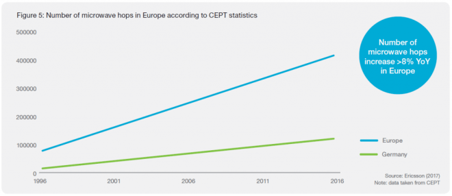
implemented using microwave. It has also been observed that usage of
lower spectrum for longer-distance hops is decreasing in favor of
higher-frequency bands for short distance and high-capacity hops.
Number of Microwave Hops in Europe according to CEPT
Spectrum trends up to 2025
Spectrum below 3GHz will provide coverage in 5G. The 3–5GHz spectrum will enable high bandwidth balanced with good coverage. These bands are not used by microwave today to any major extent (apart from some 4 and 5GHz long-haul links). The extreme bandwidths in 5G will be enabled for hotspots and industry applications in spectrum above 20GHz.
It is clear that the main focus will be on bands 24–42GHz. In the US the FCC currently has a 24, 28 and 38GHz focus and in Europe there is a focus on 26GHz. 3GPP is specifying 5G bands in 24.25–29.5GHz and 37–43.5GHz in Release 15. It excludes 32GHz and E-band, which are both part of the ITU study and, in a recent report, the FCC stresses the importance of E-band for 5G backhaul. The decision on which bands to use and where, will be unique to each nation. But longterm parts of the 24–42GHz spectrum will be used more by 5G and less by microwave fixed services. In some of these bands, e.g. 26 and 38GHz
in Europe, there are many existing microwave links in several countries.
It will take time to move these links to other bands such as E-band. The 15–23GHz spectrum will remain as the global high-volume microwave bands. E-band will become a global high-volume band, both on its own and in a multi-band booster combination with 15–23GHz.
For long hops and as an economical replacement to fiber, 6–13GHz will also remain important. Due to their good propagation properties in geographical areas with high rain rates, these low frequencies are fundamental to building transport networks in certain regions.
With all of this taken into account, it is clear that the availability and usage of microwave spectrum will go through a major transformation in the next 5 to 10 years
New deployment share per frequency range
Higher Capacities: Radio Link Aggregation
When combining data over multiple carriers, radio link bonding is a key technology. An efficient bonding technique ensures that a single data stream is seamlessly transmitted across different radio channels, with negligible overhead. In the current Global market: About 80 percent of links are configured as single carriers (1+0), the remainder as multi-carrier links with backup links as protection. About 8 percent are set up with one active radio and the protection link in hot standby mode (1+1); 10 percent are configured with dual-carrier radio link bonding (2+0), where the capacity of the backup link is used to increase the link’s peak capacity. Only 2 percent are configured for three or more carriers (>2+0). Due to the need for increased transport capacity, the number of links aggregated over two or more carriers is rising globally.
Global distribution of radio link configurations. 80 percent are configured as single-carrier links (1+0), 20 percent are configured as multiple radio links
Total Cost of Ownership (TCO) and Return-on-Investment (ROI)
The total cost of ownership and time-to-market becomes critical to
secure the overall operator business case. As fiber investments typically
have a depreciation of around 25 years, and 5–8 years for microwave,
it becomes important to invest in fiber within the right areas, such
as core and aggregation networks, which historically have been
deployed with long-haul microwave.
Technology Evolution for Microwave
Over the past 20 years, microwave technology has been continuously
evolving to meet requirements. In 1996, microwave hops typically
supported 34Mbps, whereas today products have the ability to support
up to 1Gbps in traditional bands, and up to 10Gbps with E-Band.
Microwave Technology Roadmap and Evolution
Acknowledgement
Some content is (C) Ericsson reproduced with thanks, from Ericsson Mobility Report Q4 2017
For Further Information
For More Information on Microwave Links, Please Contact Us
Alignment of Microwave Antennas for Digital Microwave Transmission Systems
This article contains generic instructions for alignment of Microwave antennas. Specific products may have different features, in which case please refer to the documentation provided for those products:
CableFree Microwave Antenna Alignment
Antenna Alignment for Microwave Links
This guide explains how to achieve the optimal antenna alignment of microwave antennas when used with modern digital microwave products. Before attempting to do the alignment it is highly recommended that you read this guide in detail. For specific commands please consult the manual of the product being installed
Step 1: Preparation:
Mount the antenna on the tower according to the antenna installation instructions: Ensure that the adjustment bolts move smoothly and the range of motion is sufficient for the expected angle of up and down (elevation) tilt. Ensure that the mount itself is attached securely and all safety precautions have been taken.
CableFree Microwave Antenna Alignment using DVM
Step 2: Coarse Alignment:
Visually align the antenna with the far end. The most common ways to do this are :
1) If the visibility is good and the sun is in the correct position, have someone at the far end location reflect the sun with a mirror so the location is obvious.
2) If visibility is poor, use GPS coordinates and a GPS compass to aim the antenna coarsely.
Before conducting fine alignment, the ODUs at both ends of the link must be attached properly to the antenna via the direct mount or remote mount (using Waveguide) and the far end ODU must be powered on and transmitting. The ODU lightning surge suppressors and grounding provisions should be put in place as well before alignment. The local ODU must be powered on, but need not be transmitting.
Ensure that:
1) Frequency of the far end transmitter matches the frequency of the local receiver.
2) The TX output power is not set above the level of the license.
3) ATPC is turned OFF on the far end.
4) Alignment mode is ON for SP ODUs – Display on ODU and IDU will update at 5 times per second.
FINE ALIGNMENT PROCEDURE
1) Adjust the azimuth over a 30 degree sweep by turning the adjustment bolt in increments of 1/10th turn to avoid missing the main lobe. When the highest signal has been found for azimuth, repeat for the elevation adjustment.
2) Turn the local transmitter on to allow alignment at the far end.
3) Move to the far end of the link and repeat step 1.
4) Lock down the antenna so no further movement can occur.
5) Install the antenna side struts supplied with the antenna.
6) Verify the RSSI remains the same and is within 2-4 dB of the expected levels.
The term ODU is used in Split-Mount Microwave systems where an Indoor Unit (IDU) is typically mounted in an indoor location (or weatherproof shelter) connected via a coaxial cable to the ODU which is mounted on a rooftop or tower top location.
CableFree Microwave ODU
Often the ODU is direct mounted to a microwave antenna using “Slip fit” waveguide connection. In some cases, a Flexible Waveguide jumper is used to connect from the ODU to the antenna.
ODU functions
The ODU converts data from the IDU into an RF signal for transmission. It also converts the RF signal from the far end to suitable data to transmit to the IDU. ODUs are weatherproofed units that are mounted on top of a tower either directly connected to a microwave antenna or connected to it through a wave guide.
Generally, Microwave ODUs designed for full duplex operation, with separate signals for transmit and receive. On the airside interface this corresponds to a “pair” of frequencies, one for transmit, the other for receive. This is known as “FDD” (Frequency Division Duplexing)
ODU Power and data signals
The ODU receives its power and the data signals from the IDU through a single coaxial cable. ODU parameters are configured and monitored through the IDU. The DC power, transmit signal, receive signal and some command/control telemetry signals are all combined onto the single coaxial cable. This use of a single cable is designed to reduce cost and time of installation.
ODu Frequency bands and sub-bands
Each ODU is designed to operate over a predefined frequency sub-band. For example 21.2 – 23.6GHz for a 23GHz system, 17.7 – 19.7GHz for a 18GHz system and 24.5 – 26.5GHz for a 26GHz system as for ODUs. The sub-band is set in hardware (filters, diplexer) at time of manufacture and cannot be changed in the field.
1+0, 1+1, 2+0 Deployments
Microwave ODUs can be deployed in various configurations.
Microwave ODU in 1+0 Configuration with Antenna
The most common is 1+0 which has a single ODU, generally connected directly to the microwave antenna. 1+0 means “unprotected” in that there is no resilience or backup equipment or path.
Two Microwave ODUs in 1+1 HSB or 2+0 configuration with Coupler and Antenna
For resilient networks there are several different configurations. 1+1 in “Hot Standby” is common and typically has a pair of ODUs (one active, one standby) connected via a Microwave Coupler to the antenna. There is typically a 3dB or 6dB loss in the coupler which splits the power either equally or unequally between the main and standby path.
Other resilient configurations are 1+1 SD (Space Diversity, using separate antennas, one ODU on each) and 1+1 FD (Frequency Diversity)
The other non-resilient configuration is 2+0 which has two ODUs connected to a single antenna via a coupler. The hardware configuration is identical to 1+1 FD, but the ODUs carry separate signals to increase the overall capacity.
Grounding & Surge Protection
Suitable ground wire should be connected to the ODU ground lug to an appropriate ground point on the antenna mounting or tower for lightning protection. This grounding is essential to avoid damage due to electrical storms.
In-line Surge Suppressors are used to protect the ODU and IDU from surges that could travel down the cable in the case of extreme surges caused by lightning
The specification of a typical Microwave ODU is shown below.
Typical ODU Features and Specifications:
4-42GHz frequency bands available
Fully synthesized design
3.5-56MHz RF channel bandwidths
Supports QPSK and 16 to 1024 QAM. Some ODUs may support 2048QAM
Standard and high power options
High MTBF, greater than 92.000 hours
Software controlled ODU functions
Designed to meet FCC, ETSI and CE safety and emission standards
Supports popular ITU-R standards and frequency recommendations
Software configurable microcontroller for ODU monitor and control settings
Low noise figure, low phase noise and high linearity
Compact and lightweight design
Very high frequency stability +/-2.5 ppm
Wide operating temperature range: -40°C to +65°C
For Further information
For More Information about Microwave ODUs, we will be delighted to answer your questions. Please Contact Us
5G Mobile networks, Microwave Backhaul and future trends in Mobile Networks
CableFree 5G Mobile Wireless Network
With 5G mobile communication becoming available around 2020, the industry has already started to develop a fairly clear view of the main challenges, opportunities and key technology components it involves. 5G will extend the performance and capabilities of wireless access networks in many dimensions, for example enhancing mobile broadband services to provide data rates beyond 10 Gbps with latencies of 1 ms.
Microwave is a key element of current backhaul networks and will continue to evolve as part of the future 5G ecosystem. An option in 5G is to use the same radio access technology for both the access and the backhaul links, with dynamic sharing of the spectrum resources. This can provide a complement to microwave backhaul especially in very dense deployments with a larger number of small radio nodes.
Today, microwave transmission dominates mobile backhaul, where it connects some 60 percent of all macro base stations. Even as the total number of connections grows, microwave’s share of the market will remain fairly constant. By 2019, it will still account for around 50 percent of all base stations (macro and outdoor small cells (see Figure 3). It will play a key role in last mile access and a complementary role the aggregation part of the network. At the same time, fibre transmission will continue to increase its share of the mobile backhaul market, and by 2019 will connect around 40 percent of all sites. Fibre will be widely used in the aggregation/metro parts of the networks and increasingly for last-mile access. There will also be geographical differences, with densely populated urban areas having higher fibre penetration than less populated suburban and rural areas, where microwave will prevail for both short-haul and long-haul links.
Spectral efficiency
CableFree 5G Mobile Backhaul Wireless Tower
Spectrum efficiency (that is, getting more bits per Hz) can be achieved through techniques like higher-order modulation and adaptive modulation, the superior system gain of a well-designed solution, and Multiple Input, Multiple Output (MIMO).
Modulation
The maximum number of symbols per second transmitted on a microwave carrier is limited by the channel bandwidth. Quadrature Amplitude Modulation (QAM) increases the potential capacity by coding bits on to each symbol. Moving from two bits per symbol (4 QAM) to 10 bits per symbol (1024 QAM) delivers a more than five-fold capacity increase.
Higher-order modulation levels have been made possible through advances in component technologies that have reduced equipment-generated noise and signal distortion. In the future there will be support for up to 4096 QAM (12 bits per symbol), but we are approaching the theoretical and practical limits. Higher-order modulation means increased sensitivity to noise and signal distortion. The receiver sensitivity is reduced by 3 dB for every increased step in modulation, while the related capacity gain gets smaller (in percentage terms). As an example, the capacity gain is 11 percent when moving from 512 QAM (9 bits per symbol) to 1024 QAM (10 bits per symbol).
Adaptive modulation
CableFree Microwave Link installed on a telecom tower
Increasing modulation makes the radio more sensitive to propagation anomalies such as rain and multi-path fading. To maintain microwave hop length, the increased sensitivity can be compensated for by higher output power and larger antennas. Adaptive modulation is a very cost-effective solution to maximize throughput in all propagation conditions. In practice, adaptive modulation is a prerequisite for deployment with extreme high-order modulation.
Adaptive modulation enables an existing microwave hop to be upgraded from, for example, 114 Mbps to as much as 500 Mbps. The higher capacity comes with lower availability. For example, availability is reduced from 99.999 percent (5 minutes’ yearly outage) at 114 Mbps to 99.99 percent of the time (50 minutes’ yearly outage) at 238 Mbps. System gain Superior system gain is a key parameter for microwave. A 6 dB higher system gain can be used, for example, to increase two modulation steps with the same availability, which provides up to 30 percent more capacity. Alternatively it could be used to increase the hop length or decrease the antenna size, or a combination of all. Contributors to superior system gain include efficient error correction coding, low receiver noise levels, digital predistortion for higher output power operation, and power-efficient amplifiers, among others.
MIMO Multiple Input, Multiple Output (MIMO)
MIMO is a mature technology that is widely used to increase spectral efficiency in 3GPP and Wi-Fi radio access, where it offers a cost-effective way to boost capacity and throughput where available spectrum is limited. Historically, the spectrum situation for microwave applications has been more relaxed; new frequency bands have been made available and the technology has been continuously developed to meet the capacity requirements. However in many countries the remaining spectrum resources for microwave applications are starting to become depleted and additional technologies are needed to meet future requirements. For 5G Mobile Backhaul, MIMO at microwave frequencies is an emerging technology that offers an effective way to further increase spectrum efficiency and so the available transport capacity.
Unlike ‘conventional’ MIMO systems, which are based on reflections in the environment, for 5G Mobile Backhaul, channels are ‘engineered’ in point-to-point microwave MIMO systems for optimum performance. This is achieved by installing the antennas with a spatial separation that is hop distance-and frequency-dependent. In principle, throughput and capacity increase linearly with the number of antennas (at the expense of additional hardware cost, of course). An NxM MIMO system is constructed using N transmitters and M receivers. Theoretically there is no limit for the N and M values, but since the antennas must be spatially separated there is a practical limitation depending on tower height and surroundings. For this reason 2×2 antennas is the most feasible type of MIMO system. These antennas could either be single polarized (two carrier system) or dual polarized (four carrier system). MIMO will be a useful tool for scaling microwave capacity further, but is still at an early phase where, for example, its regulatory status still needs to be clarified in most countries, and its propagation and planning models still need to be established. The antenna separation can also be challenging especially for lower frequencies and longer hop lengths.
More Spectrum
Another section of the microwave capacity toolbox for 5G Mobile Backhaul involves getting access to more spectrum. Here the millimeter-wave bands – the unlicensed 60 GHz bands and the licensed 70/80 GHz band – are growing in popularity as a way of getting access to new spectrum in many markets (see Microwave Frequency Options section for more information). These bands also offer much wider frequency channels, which facilitate deployment of cost-efficient, multi-gigabit systems which enable 5G Mobile Backhaul.
Throughput efficiency
Throughput efficiency (that is, more payload data per bit), involves features like multi-layer header compression and radio link aggregation/bonding, which focus on the behaviour of packet streams.
Multi-layer header compression
Multi-layer header compression removes unnecessary information from the headers of the data frames and releases capacity for traffic purposes, as shown in Figure 7. On compression, each unique header is replaced with a unique identity on the transmitting side, a process which is reversed on the receiving side. Header compression provides relatively higher utilization gain for packets of smaller frame size, since their headers comprise a relatively larger part of the total frame size. This means the resulting extra capacity varies with the number of headers and frame size, but is typically a 5–10 percent gain with Ethernet, IPv4 and WCDMA, with an average frame size of 400–600 bytes, and a 15–20 percent gain with Ethernet, MPLS, IPv6 and LTE with the same average frame size.
These figures assume that the implemented compression can support the total number of unique headers that are transmitted. In addition, the header compression should be robust and very simple to use, for example offering self-learning, minimal configuration and comprehensive performance indicators.
Radio Link Aggregation (RLA, Bonding)
Radio link bonding in microwave is akin to carrier aggregation in LTE and is an important tool to support continued traffic growth, as a higher share of microwave hops are deployed with multiple carriers, as illustrated in Figure 8. Both techniques aggregate multiple radio carriers into one virtual one, so both enhancing the peak capacity as well as increasing the effective throughput through statistical multiplexing gain. Nearly 100 percent efficiency is achieved, since each data packet can use the total aggregated peak capacity with only a minor reduction for protocol overhead, independent of traffic patterns. Radio link bonding is tailored to provide superior performance for the particular microwave transport solution concerned. For example, it may support independent behaviour of each radio carrier using adaptive modulation, as well as graceful degradation in the event of failure of one or more carrier (N+0 protection).
Just like carrier aggregation, radio link bonding will continue to be developed to support higher capacities and more flexible carrier combinations, for example through support for aggregation of more carriers, carriers with different bandwidths and carriers in different frequency bands.
Network optimization
The next section of the capacity toolbox is network optimization. This involves densifying networks without the need for extra frequency channels through interference mitigation features like super high performance (SHP) antennas and automatic transmit power control (ATPC). SHP antennas effectively suppress interference through very low sidelobe radiation patterns, fulfilling ETSI class 4. ATPC enables the transmit power to be automatically reduced during favorable propagation conditions (that is, most of the time), effectively reducing the interference in the network. Using these features reduces the number of frequency channels needed in the network and could deliver up to 70 percent more total network capacity per channel. Interference due to misalignment or dense deployment is limiting backhaul build-out in many networks. Careful network planning, advanced antennas, signal processing and the use of ATPC features at a network level will reduce the impact from interference.
Looking to the future, 5G and Beyond
CableFree 5G Mobile Wireless Technology
Over the coming years, microwave capacity tools for 5G Mobile Networks will be evolved and enhanced, and used in combination enabling capacities of 10 Gbps and beyond. Total cost of ownership will be optimized for common high-capacity configurations, such as multi-carrier solutions.
To deliver a compelling quality of experience for subscribers, you must respond quickly to growing traffic demands. Modern Packet Microwave Mobile Backhaul products help you maximize the network’s performance by enabling rapid deployment of scalable backhaul to cell sites. Modern solutions include a portfolio of microwave products to address the backhaul needs of 2G, 3G, and LTE macro cells and 3G, LTE, and Wi-Fi® small cells. Radio spectrum is maximized using innovative techniques to maximize payload capacity to support the evolution to LTE and heterogeneous networks. Unique, common radio support for indoor and outdoor deployments enhances savings potential.
Packet Microwave Mobile Backhaul is a key component in a modern end-to-end mobile backhaul solution, which provides the flexibility, scale and operational simplicity to lower the total cost of ownership and simultaneously enhance the mobile service experience.
BENEFITS
CableFree Microwave for Mobile Backhaul
Economic benefits
Rapidly support the optimal cell site location
Complete backhaul portfolio for macro cells and small cells
Support for all sites including both end and intermediate cell sites
Space and power efficiency
Full outdoor option to meet different microwave site space requirements
Achieve maximum spectral performance
Maximum bandwidth per band
Intelligent compression
Advanced quality of service levels supporting subscriber quality of experience
Scale the network cost effectively
Reliably bond radio channels to create larger microwave links
Any topology, any number of microwave link directions
Network awareness for both Carrier Ethernet and/or IP/MPLS networks
Be operationally efficient
Common radio for all cell sites
Evolutionary path from hybrid microwave to packet microwave at the touch of a button
Management beyond basic IP partner integration
Deployment, management, end-user benefits
Grow and retain subscribers by maximizing the mobile experience
Infrastructure support for increased subscriber bandwidth demands
Ability to react quickly to subscriber demand with optimally-located cell sites
Increased capacity that supports high bandwidth data applications
COMPONENTS
4G/LTE Mobile Backhaul
Packet Microwave Mobile Backhaul integrates a modern microwave portfolio with small cell optimized products to provide a complete backhaul offering for small cells and/or macro cells.
Read on in our following pages to find out more about technologies used in mobile backhaul applications


You must be logged in to post a comment.