Microwave Antenna Alignment

Alignment of Microwave Antennas for Digital Microwave Transmission Systems

This article contains generic instructions for alignment of Microwave antennas.  Specific products may have different features, in which case please refer to the documentation provided for those products:

CableFree Microwave Antenna Alignment

Antenna Alignment for Microwave Links

This guide explains how to achieve the optimal antenna alignment of microwave antennas when used with modern digital microwave products.  Before attempting to do the alignment it is highly recommended that you read this guide in detail.  For specific commands please consult the manual of the product being installed

Step 1:  Preparation:

Mount the antenna on the tower according to the antenna installation instructions:  Ensure that the adjustment bolts move smoothly and the range of motion is sufficient for the expected angle of up and down (elevation) tilt. Ensure that the mount itself is attached securely and all safety precautions have been taken.

CableFree Microwave Antenna Alignment using DVM

Step 2: Coarse Alignment:

Visually align the antenna with the far end.  The most common ways to do this are :

1)      If the visibility is good and the sun is in the correct position, have someone at the far end location reflect the sun with a mirror so the location is obvious.

2)      If visibility is poor, use GPS coordinates and a GPS compass to aim the antenna coarsely.

CableFree Microwave Antenna Alignment avoiding Sidelobes

Step 3: Fine Alignment.

Before conducting fine alignment, the ODUs at both ends of the link must be attached properly to the antenna via the direct mount or remote mount (using Waveguide) and the far end ODU must be powered on and transmitting.  The ODU lightning surge suppressors and grounding provisions should be put in place as well before alignment. The local ODU must be powered on, but need not be transmitting.

Ensure that:

1)      Frequency of the far end transmitter matches the frequency of the local receiver.

2)      The TX output power is not set above the level of the license.

3)      ATPC is turned OFF on the far end.

4)      Alignment mode is ON for SP ODUs – Display on ODU and IDU will update at 5 times per second.

FINE ALIGNMENT PROCEDURE

1)      Adjust the azimuth over a 30 degree sweep by turning the adjustment bolt in increments of 1/10th turn to avoid missing the main lobe. When the highest signal has been found for azimuth, repeat for the elevation adjustment.

2)      Turn the local transmitter on to allow alignment at the far end.

3)      Move to the far end of the link and repeat step 1.

4)      Lock down the antenna so no further movement can occur.

5)      Install the antenna side struts supplied with the antenna.

6)      Verify the RSSI remains the same and is within 2-4 dB of the expected levels.

7)      Check the ODU connector seals.

8)      Turn alignment mode OFF

9)      The alignment is complete.

FDD and TDD Explained

The difference between FDD and TDD in Microwave Transmission

Microwave ODU with Antenna using FDD (Frequency Division Duplex)

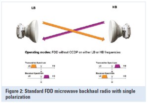
Microwave links typically use Frequency-division duplexing (FDD) which is a method for establishing a full-duplex communications link that uses two different radio frequencies for transmitter and receiver operation. The transmit direction and receive direction frequencies are separated by a defined frequency offset.

Advantages of FDD

In the microwave realm, the primary advantages of this approach are:

  • The full data capacity is always available in each direction because the send and receive functions are separated;
  • It offers very low latency since transmit and receive functions operate simultaneously and continuously;
  • It can be used in licensed and license-exempt bands;
  • Most licensed bands worldwide are based on FDD; and
  • Due to regulatory restrictions, FDD radios used in licensed bands are coordinated and protected from interference, though not immune to it.
Microwave FDD (Frequency Division Duplexing)

Disadvantages to FDD

The primary disadvantages of the FDD approach to microwave communication are:

  • Complex to install. Any given path requires the availability of a pair of frequencies; if either frequency in the pair is unavailable, then it may not be possible to deploy the system in that band;
  • Radios require pre-configured channel pairs, making sparing complex;
  • Any traffic allocation other than a 50:50 split between transmit and receive yields inefficient use of one of the two paired frequencies, lowering spectral efficiency; and
  • Collocation of multiple radios is difficult.

TDD compared with FDD

Time-division duplexing (TDD) is a method for emulating full-duplex communication over a half-duplex communication link. The transmitter and receiver both use the same frequency but transmit and receive traffic is switched in time. The primary advantages of this approach as it applies to microwave communication are:

  • It is more spectrum friendly, allowing the use of only a single frequency for operation and dramatically increasing spectrum utilization, especially in license-exempt or narrow-bandwidth frequency bands ;
  • It allows for the variable allocation of throughput between the transmit and receive directions, making it well suited to applications with asymmetric traffic requirements, such as video surveillance, broadcast and Internet browsing;
  • Radios can be tuned for operation anywhere in a band and can be used at either end of the link. As a consequence, only a single spare is required to serve both ends of a link.

Disadvantages of TDD

The primary disadvantages of traditional TDD approaches to microwave communications are:

  • The switch from transmit to receive incurs a delay that causes traditional TDD systems to have greater inherent latency than FDD systems;
  • Traditional TDD approaches yield poor TDM performance due to latency;
  • For symmetric traffic (50:50), TDD is less spectrally efficient than FDD, due to the switching time between transmit and receive; and
  • Multiple co-located radios may interfere with one another unless they are synchronized.


Microwave ODU

Microwave ODU (Outdoor Unit)

The term ODU is used in Split-Mount Microwave systems where an Indoor Unit (IDU) is typically mounted in an indoor location (or weatherproof shelter) connected via a coaxial cable to the ODU which is mounted on a rooftop or tower top location.

CableFree Microwave ODU

Often the ODU is direct mounted to a microwave antenna using “Slip fit” waveguide connection.  In some cases, a Flexible Waveguide jumper is used to connect from the ODU to the antenna.

ODU functions

The ODU converts data from the IDU into an RF signal for transmission. It also converts the RF signal from the far end to suitable data to transmit to the IDU. ODUs are weatherproofed units that are mounted on top of a tower either directly connected to a microwave antenna or connected to it through a wave guide.

Generally, Microwave ODUs designed for full duplex operation, with separate signals for transmit and receive.  On the airside interface this corresponds to a “pair” of frequencies, one for transmit, the other for receive.  This is known as “FDD” (Frequency Division Duplexing)

ODU Power and data signals

The ODU receives its power and the data signals from the IDU through a single coaxial cable. ODU parameters are configured and monitored through the IDU.  The DC power, transmit signal, receive signal and some command/control telemetry signals are all combined onto the single coaxial cable.  This use of a single cable is designed to reduce cost and time of installation.

ODu Frequency bands and sub-bands

Each ODU is designed to operate over a predefined frequency sub-band. For example 21.2 – 23.6GHz for a 23GHz system, 17.7 – 19.7GHz for a 18GHz system and 24.5 – 26.5GHz for a 26GHz system as for ODUs.    The sub-band is set in hardware (filters, diplexer) at time of manufacture and cannot be changed in the field.

1+0, 1+1, 2+0 Deployments

Microwave ODUs can be deployed in various configurations.

Microwave ODU in 1+0 Configuration with Antenna

The most common is 1+0 which has a single ODU, generally connected directly to the microwave antenna.  1+0 means “unprotected” in that there is no resilience or backup equipment or path.


Two Microwave ODUs in 1+1 HSB or 2+0 configuration with Coupler and Antenna

For resilient networks there are several different configurations.  1+1 in “Hot Standby” is common and typically has a pair of ODUs (one active, one standby) connected via a Microwave Coupler to the antenna.  There is typically a 3dB or 6dB loss in the coupler which splits the power either equally or unequally between the main and standby path.

Other resilient configurations are 1+1 SD (Space Diversity, using separate antennas, one ODU on each) and 1+1 FD (Frequency Diversity)

The other non-resilient configuration is 2+0 which has two ODUs connected to a single antenna via a coupler.  The hardware configuration is identical to 1+1 FD, but the ODUs carry separate signals to increase the overall capacity.

Grounding & Surge Protection

Suitable ground wire should be connected to the ODU ground lug to an appropriate ground point on the antenna mounting or tower for lightning protection.  This grounding is essential to avoid damage due to electrical storms.

In-line Surge Suppressors are used to protect the ODU and IDU from surges that could travel down the cable in the case of extreme surges caused by lightning

The specification of a typical Microwave ODU is shown below.

Typical ODU Features and Specifications:

  • 4-42GHz frequency bands available
  • Fully synthesized design
  • 3.5-56MHz RF channel bandwidths
  • Supports QPSK and 16 to 1024 QAM.  Some ODUs may support 2048QAM
  • Standard and high power options
  • High MTBF, greater than 92.000 hours
  • Software controlled ODU functions
  • Designed to meet FCC, ETSI and CE safety and emission standards
  • Supports popular ITU-R standards and frequency recommendations
  • Software configurable microcontroller for ODU monitor and control settings
  • Low noise figure, low phase noise and high linearity
  • Compact and lightweight design
  • Very high frequency stability +/-2.5 ppm
  • Wide operating temperature range: -40°C to +65°C

For Further information

For More Information about Microwave ODUs, we will be delighted to answer your questions. Please Contact Us